A new non-regulated fibre for use in iron and steel as 1430 °C RCF substitute
Throughout the last few decades RCF (Refractory Ceramic Fibre) also known as ASW (Alumino Silicate Wool) has been considered the stateoftheart material for lining reheating kilns for steel, such as forging shuttle kilns. This is largely due to its excellent properties, which include low thermal conductivity and thermal mass, low density and ease of installation, providing a highly adaptable insulation system.
Due to proven concerns with asbestos, fbrous materials were placed under scrutiny and RCF was given high priority as it was used in many applications asbestos had been used in. After numerous studies, RCF was classifed as a category 1b carcinogen in Europe and is considered a substance of very high concern (SVHC) under REACH (Registration, Evaluation, Authorisation and Restriction of Chemicals).
With the frst generation of low biopersistent AES (alkaline earth silicate) fbre types, a strong alternative was introduced to the market in the 1990s. However it was found that both AES had low temperature use limits (initially approximately 1000 °C) and their resistance to pollutants, especially with alkalis, was poor, limiting potential usage in many applications especially for the Iron and Steel industry.
Further improvements to AES fbres have been introduced to the market, improving their use limit to 1150 °C, but all AES fbres still have the problem of poor pollution resistance. Morgan’s Thermal Ceramics Product Division, has continued to develop low biopersistent fbre insulation and is now extending its product range with a new high temperature fbre called Superwool® XT. The latter has a classifcation temperature of 1450 °C and comparative if not better pollution resistance than RCF. Superwool® XT was put to the test in a feld trial using stack modules in shuttle kilns operating at 1280 °C, at Dillinger, Dillingen/ Saar in Germany. Results showed that Superwool® XT demonstrated excellent performance in the harsh conditions found within this application.
1 Introduction
As a category 1b carcinogen, falling under the scope of the Carcinogens and Mutagens Directive (2004/37/EC), RCF is now the subject of a proposal to tighten occupational exposure limits from 1 fbre/ml to 0,3 fbre/ml in the EU and remains listed as a substance of very high concern under REACH regulation (1907/2006/EC). Other countries also continue to review the regulation of the use of RCF, including Japan, Australia, South Korea and Brazil. These countries have either introduced or amended the regulation and control of RCF. For example, Japan has introduced a stringent workplace use policy, with users required to show compliance with a 0,3 fbres/ml occupational exposure limit, as well as providing additional amenities for worker hygiene, segregating work areas for RCF use and instigating a worker health surveillance programme. These regulations increase pressure on multinational users of RCF to seek alternatives wherever possible.
Europe remains the only regulatory arena to provide a route of exoneration for manmade vitreous (silicate) fbres (MMVFs) containing more than 18 % alkaline earth oxide [1]. Using bioassays to demonstrate low biopersistence and/or a lack of pathogenicity. Other countries use a weight of evidence in their assessment of MMVFs. All Superwool® fbres are exonerated from classifcation in Europe and unclassifed throughout the rest of the world [2].
Superwool® XT has been developed as a low biopersistent fbre with 1450 °C classifcation temperature capable of replacing Cerachem®. It has less than 18 % alkali metal oxide and has been tested and exonerated according to EU protocol ECB/TM/27 (rev 7). It is a potassium aluminosilicate based fbre with a melting point in excess of 1650 °C. Customer trials have been ongoing in many applications, which began in 2015. Extensive internal testing of fbres fred from 900–1400 °C has shown no crystalline silica forms even after almost one year at temperature. Its physical properties as a blanket and in module form are very similar to RCF and other AES fbres. Superwool® XT also has a unique behaviour that is benefcial, courtesy of its higher thermal expansion coeffcient. It exhibits a small expansion on heating up to high temperatures that counteracts the irreversible shrinkage. Any shrinkage gaps between modules close up as the furnace heats. This means that there is no need to fll shrinkage gaps, as is the usual practice, in an RCF installation shortly after commissioning. Superwool® XT is also more resistant to many pollutants (especially alkalis) than RCF at high temperatures and this results in a more stable furnace lining over time. The latter is covered in more detail below.
2 Chemical resistance
Resistance to pollutants at high temperatures is a very important property for fbrous insulation, particularly since it is installed and used as modules or blanket. As such the insulation has a relatively high surface area compared to bricks and monolithics and is porous to infltration of pollutants in the furnace atmosphere. This makes fbrous insulation particularly vulnerable to chemical attack. It is important to be able to assess how resistant any new fbre composition is to pollutants and to understand which pollutants are a problem prior to installing them in a customer application. A method based on one used by a Polycrystalline Wool (PCW) producer is used by Morgan’s Thermal Products Division. In this test a blanket sample is immersed in water containing 3 % of the pollutant in the form of a water soluble salt (e.g. nitrate, chloride, carbonate). This is then dried at 110 °C, which results in a pollutant pick up of ~10 mass%. This is the equivalent of ~2–10 years exposure in a heavily polluted furnace (Tab. 1).
Tab. 1. Pollution resistance of Superwool® XT versus Cerachem® at 1300 °C/24 h
Pollutant | Superwool® XT | Cerachem® | Superwool® XT VS |
Pb | | | Superwool® XT better |
Na | | | Superwool® XT |
Mn | | | Superwool® XT |
Ni | | | Same |
Sn | | | Same |
K | | | Same |
Fe | | | Same |
Cr | | | Same |
Bi | | | Same |
B | | | Same |
Cu | | | Same |
V | | | Same |
P | | | Cerachem® |
Zn | | | Cerachem® |
Mo | | | Cerachem® |
The blanket sample is then linear shrinkage tested at both the classifcation and continuous use temperature and the sample assessed via linear and thickness shrinkage (>4 % linear and/or >10 % thickness is poor) and crystallisation (assessed by ability to handle blanket without damaging it).
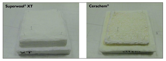
Fig. 1. Pollution testing with sodium at 1300 °C/24 h
A typical test result for sodium attack is demonstrated in a number of selected pollutants; including sodium, potassium, boron, iron and many more. Superwool® XT was found to be similar or better than Cerachem® with 12 of the 15 pollutants tested. Tab. 1 shows a comparison between Superwool® XT and Cerachem® for all the pollutants tested at 1300 °C, the top continuous use temperature of these two fibre types.
3 Industrial application
As mentioned, new EHS regulations drive operators and also installers to fnd alternatives for RCF [3]. Whilst IFB or insulating monolithics often do not meet the requirements of flexibility of the insulation in in dustrial applications, solutions implying the use of PCW’s are often limited for economic reasons as the price of PCW is known to be in the range of 5–10 times higher than established RCF solutions. Regarding restricted furnace operation flexibility (duration of heating cycles, hot charging vs. thermal shock resistance of lining) in the past a combination of RCF with PCW was often used to compensate for RCF’s temperature and pollutantresilience constraints. These combined modules consisting of PCW as the front layer with an RCF backup, have been widely used instead of full PCW modules to keep costs on an acceptable level for the furnace operators. In light of EHS regulations today this is often not accepted because large quantities of RCF fbres are released into the environment during installation and wrecking.
Combined modules consisting of PCW and available AES fbre types have been found unsuitable due to chemical cross reaction between those materials, resulting in lining failures.
3.1 Industrial feld trial: Dillinger
Dillinger, located in Dillingen/DE operates a mill for heavy plates. Annual tonnage is around 1,9 million, milled to customers’ needs. Reheating is carried out in three pusher type furnaces lined with monolithic refractories. As Dillinger is also producing special grades and sizes, with prematerial being produced using the bottom pouring ingot casting route, three additional shuttle kilns are available for reheating ingots as well as slabs on high load events or during downtime of pusher furnaces. These kilns were built in the early 2000’s over a period of several years. The original linings were made from Cerachem® stack modules with a monolithic gate and monolithic preformed burner blocks.
The furnaces are typically operated at a nominal temperature between 1250–1300 °C using blast furnace and coking gas as primary fuels. Hot charging of the furnaces is performed regularly. A cool down is only instigated for maintenance reasons, every few weeks when required.
Charging of the furnaces, as well as the roller path, roughing stand and pusher type furnaces nearby, result in a high mechanical stress for the lining. A severe issue is the presence of multiple impurities in the atmospheres of these furnaces, particularly alkalis (sodium and potassium) but also iron and chromium which come from residual casting powders stuck to the ingots being reheated as well as the steel itself. These impurities end up in the hot face of the lining and result in increased shrinkage over time and hardening/densifcation of the module front face. This is then subjected to thermal shock, cracking and spalling.
Tab. 2. Chemical composition of Cerachem®
| Weight (%) | Typical | After 4 years |
| Na2O | - | 7,3 |
| Al2O3 | 36,3 | 16,2 |
| SiO2 | 49,3 | 54 |
| SO3 | - | 1,8 |
| K2O | - | 1,4 |
| Fe2O3 | - | 4,1 |
| ZrO2 | 14,8 | 15,2 |
Tab. 2 compares the chemical composition of a “typical as delivered” module versus one exposed to four years of use in a shuttle kiln at Dillinger.
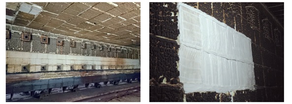
Fig. 2. Typical appearance of lining after several years of operation, here shuttle kiln No. 1
Fig. 3. Finished test-feld lined with Superwool® XT stack modules
In Fig. 2, the appearance of the lining after several years of service is shown. It is apparent that major repairs have been carried out, including module replacement and gap flling. The high shrinkage resulting in open gaps also causes the module anchor system to become unstable as the latter become exposed to higher temperatures than they are designed for.
3.1.1 Initial feasibility test in side wall of shuttle kiln No. 2
Dillinger was one of the frst customers chosen to test Superwool® XT in their furnaces. It was agreed to start with a small section of the wall in shuttle kiln No. 2, where the risk of any problems resulting in long downtime issues was considered to be low.
Two rows of fve Superwool® XT stack modules with type T anchors were installed with 1 Cerachem® stack module with type Y anchor fnishing each row for comparison of results. Fig. 3 demonstrates that due to high shrinkage of the surrounding existing lining, it was necessary to fll the large shrinkage gaps, with several folds made from PCW blanket. In between the two rows, one fold of PCW blanket was placed. Shrinkage of modules was found to be approximately 1,3 % after about two months of fring. On further inspection, after six months of fring, it was determined that Superwool® XT shrinkage had increased to 4 % whilst Cerachem® had shown a shrinkage of 5,7 % at this stage. A further notable difference in the appearance became obvious at this stage: in Fig. 4 the surface of both materials is shown. Whilst the surface of Cerachem® had hardened signifcantly, with large cracks forming on the surface, the appearance of Superwool® XT was quite different, showing a surface that remained soft and partly resilient, with no surface shrinkage cracks. It was also clear that Superwool® XT was not absorbing large levels of pollutants from the furnace atmosphere and the module colour remained a light grey from minor iron pick up. This is unlike the Cerachem® modules which rapidly became dark brown in colour and eventually went black like the rest of the Cerachem® modules in the furnace lining. In Fig. 5 the appearance of the feld at this state is shown. Marked damage is due to samples being removed for laboratory testing purposes and does not indicate poor performance of any of the materials under test.
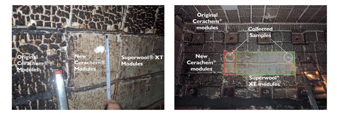
Fig. 4. Surface of Cerachem® (l.) and Superwool® XT (r.) after 6 months in service
Fig. 5. Overall appearance after six months in service
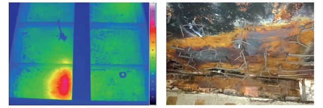
Fig. 6. Infra-red thermography of roof of shuttle kiln No. 3
Fig. 7. Example of damaged steel shell which made partreplacement necessary
3.1.2 Installation of half of the roof of shuttle kiln No. 3 at Dillinger
Based on the positive experience when installing Superwool® XT in the side wall of shuttle kiln No. 2, Dillinger mill operations decided to reline half of the roof of shuttle kiln No. 3 with the newly developed Superwool® XT.
The old lining was wrecked, bagged up and disposed of as hazardous waste – something which becomes increasingly important to take into cost considerations today. Due to RCF’s carcinogen status, special provisions have to be adopted, e.g. cover of the entire furnace for installation and wrecking work, to prevent RCF fbres entering the surrounding workplace. Specialist disposal is required for both the old lining and any protective clothing used each day. The creation of black and white areas for involved personnel may also be necessary to prevent crossover of material to the general workplace. This can easily cost an organisation several thousand Euros and was not previously a consideration of the cost of ownership of an RCF lined furnace; but certainly needs to be factored in now. Due to the high shrinkage of the Cerachem® modules resulting in open gaps between the modules, even when the furnace was hot, the steel shell had gradually become damaged and replacement was necessary in many areas. The roof is usually the hottest area of the furnace and most susceptible to thermal damage. Hotspots were found using a thermal vision scan of the furnace roof and an example is shown in Fig. 6. The damage to the steel shell, is shown in Fig. 7.
The refractory insulation lining is constructed using a backup of lower temperature classifcation board and blanket – 1 mm × 25 mm layer of blanket and board, with 250 mm thick stack modules made from Superwool® XT as the hot face lining. A single fold of PCW blanket is installed in between each row of modules to avoid open gaps due to shrinkage. The furnace after relining before it went back into service is shown in Fig. 8.
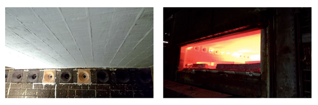
Fig. 8. Finished roof, Superwool® XT stack modules with PCW blanket fold in between
Fig. 9. Shuttle kiln No. 3 in service at 1280 °C
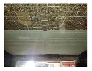
Fig. 10. Appearance after 6 months in service
At maximum temperature, the furnace shows distinct hot spots above the burners, as can be observed in Fig. 9. After 6 months of service, frst inspection of this second installation was possible. The new lining was in a good state and no additional gap flling has been required at any stage so far. This second Superwool® XT installation has now been working for 10 months. Fig. 10 highlights the good appearance of the roof after six months of service.
4 Conclusions and future outlook
Results presented here have shown that there is now a nonregulated high temperature fbre alternative to RCF, the latter’s use being viewed as increasingly problematical due to environmental, health and safety issues. Dillinger has now decided, to switch entirely to the new Superwool® XT grade, for the beneft of both the nonregulated status of this product and its superior chemical resistance and shrinkage performance, relative to RCF. The refractory maintenance department managers at Dillinger are therefore very happy to present to their EHS department a working alternative that will reduce risk for the workers as well as costs for installation, wrecking and disposal.
Further positive results have been obtained in other felds, such as the petrochemical industries, with successful trials in advanced stages at numerous reformers and crackers. Superwool® XT will help customers to meet the requirements of replacement regulations (e.g. European regulation 619: Substitute materials for alumino silicate wool
products). Furthermore, the performance drop expected from fbres with low biopersistence has not been observed in the applications under test so far. On the contrary, it was shown that the material is outperforming existing RCF solutions in environments with high pollutant levels.
References:
[1] Regulation (EC) No. 1272/2008 of the European Parliament and of the Council of 16 December 2008 on classifcation, labelling and packaging of substances and mixtures
[2] Superwool products all full under harmonized classifcation and labelling entry written CLP under index number 6500160002
[3] Alexander, I.C.; Jubb, G.: Development of soluble high temperature fbre. Glastechn. Ber. 70 (1997) [12] 382–388
Refractories worldforum 9 (2017)
Peter Ermtraud, Gary Jubb, Nicola Robinson